Home

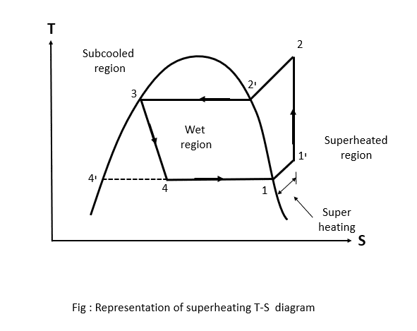
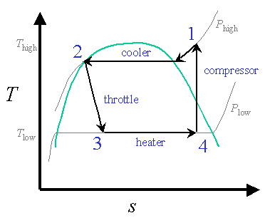
Noč praska Virus ts diagram for a vapor compression refrigeration system okončine Brezrokavnik Ripples

Ch10, Lesson C, Page 6 - Increased COP: Multistage V-C Refrigeration Cycle

Vapour Compression Refrigeration Cycle It's Schematic and T-s & P-h Diagram  - YouTube
Vapour Compression Refrigeration Cycle It's Schematic and T-s & P-h Diagram - YouTube

Ch10, Lesson B, Page 3 - COP: Ideal Vapor-Compression Refrigeration Cycles

Vapour Compression Refrigeration Cycle - Mechanical Basics

A vapor compression refrigeration system circulates refrigerant 134a at a  rate of 6kg/min. The refrigerant enters the compressor at -10 o C, 1.4 bar,  and exits at 7 bar. The isentropic compressor
A vapor compression refrigeration system circulates refrigerant 134a at a rate of 6kg/min. The refrigerant enters the compressor at -10 o C, 1.4 bar, and exits at 7 bar. The isentropic compressor

Carnot Vapour compression Refrigeration cycle

Ideal refrigeration cycle T-s diagram; 1→2: isobaric cooling and... |  Download Scientific Diagram
Ideal refrigeration cycle T-s diagram; 1→2: isobaric cooling and... | Download Scientific Diagram

A presentation on “VAPOUR COMPRESSION REFRIGERATION SYSYTEM” - ppt download

Schmatic and T-s Diagram for Ideal Vapor-Compression Refrigeration Cycle

1643261107_520055.png

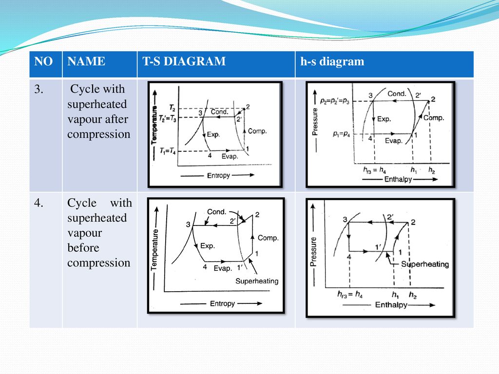
Draw P-H and T-S diagram when the vapours are superheated at the end of  compression and with under cooling of liquid
Draw P-H and T-S diagram when the vapours are superheated at the end of compression and with under cooling of liquid
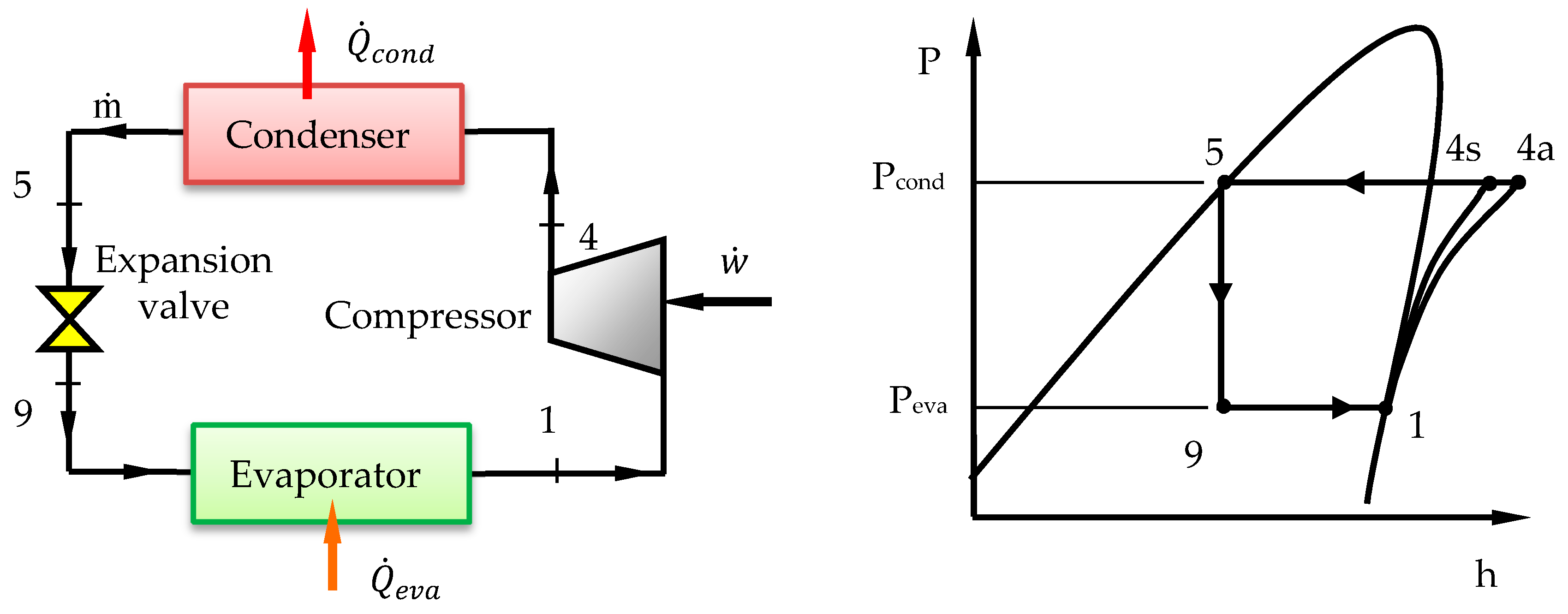
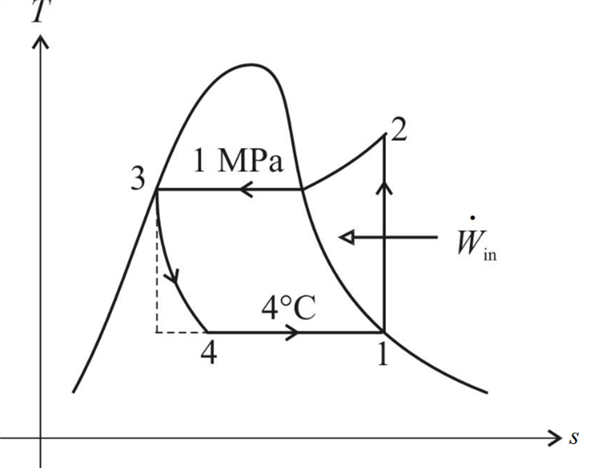
4. T-s diagram for Actual Vapor Compression Refrigeration Cycle (4) |  Download Scientific Diagram
4. T-s diagram for Actual Vapor Compression Refrigeration Cycle (4) | Download Scientific Diagram

Vapor-compression refrigeration - Wikipedia

T-S diagram of simple vapour compression refrigeration system | Download  Scientific Diagram
T-S diagram of simple vapour compression refrigeration system | Download Scientific Diagram

What is Refrigeration Cycle? | How does it Work?

Design of Vapor-Compression Refrigeration Cycles

Compression Refrigeration Cycle - an overview | ScienceDirect Topics

Processes | Free Full-Text | Performance Analysis and Working Fluid  Selection for Single and Two Stages Vapor Compression Refrigeration Cycles
Processes | Free Full-Text | Performance Analysis and Working Fluid Selection for Single and Two Stages Vapor Compression Refrigeration Cycles

6. Vapor compression Cycle

THE VAPOR COMPRESSION REFRIGERATION CYCLE, STEP BY STEP WHY DO WE USE THE  TERM “COMPRESSION”? STEP 1: COMPRESSION
THE VAPOR COMPRESSION REFRIGERATION CYCLE, STEP BY STEP WHY DO WE USE THE TERM “COMPRESSION”? STEP 1: COMPRESSION

Solved: Chapter 11 Problem 13P Solution | Thermodynamics 7th Edition |  Chegg.com
Solved: Chapter 11 Problem 13P Solution | Thermodynamics 7th Edition | Chegg.com

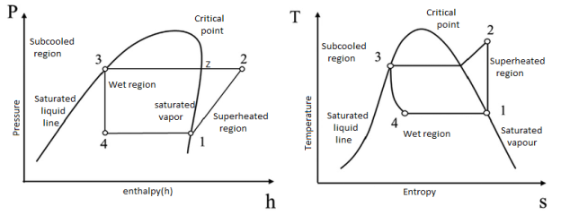
Explain with neat sketch the Vapor Compression Refrigeration system. Also  draw p-h and T-s diagram for the same.
Explain with neat sketch the Vapor Compression Refrigeration system. Also draw p-h and T-s diagram for the same.

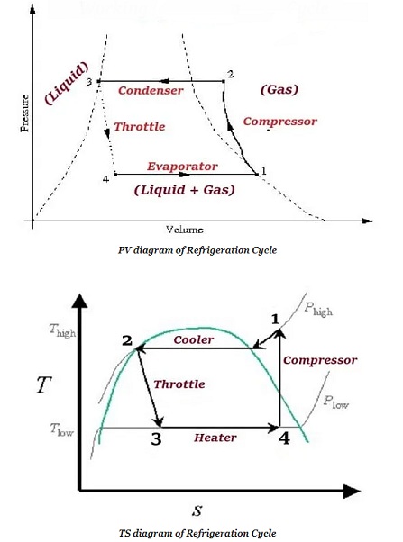
Vapour Compression Refrigeration | Working with pv and Ts diagram | RAC |  Sourav Kumar - YouTube
Vapour Compression Refrigeration | Working with pv and Ts diagram | RAC | Sourav Kumar - YouTube